


Product Summary:
The working principle of eddy current linear displacement sensor system is eddy current effect, which belongs to an inductive measurement principle. The eddy current effect results from the energy of the oscillating circuit. Eddy currents need to be formed in conductive materials. An alternating current is introduced into the inner coil of the sensor probe to create a magnetic field around the probe coil. If you put a conductor in this field, according to Faraday's law of electromagnetic induction, eddy currents will be excited within the conductor. According to Lenz's law, the direction of the eddy current's magnetic field is opposite to the coil's magnetic field, and this will change the impedance value of the coil inside the probe. The change in this impedance value is directly related to the distance between the coil and the object being measured. After the sensor probe is connected to the controller, the controller can obtain the variation of voltage value from the sensor probe and calculate the corresponding distance value based on it. The principle of eddy current measurement can measure all conductive materials. Because the eddy current can penetrate the insulator, even if the surface is covered with the metal material of the insulator, it can also be used as the object of the eddy current sensor. The unique coil winding design not only realizes the good and compact shape of the sensor, but also can meet the requirements of its operation in the high temperature measurement environment.
- Product Overview
- Technical Parameters
- Size selection
Working principle:
The working principle of eddy current sensor system is eddy current effect, which belongs to an inductive measurement principle. The eddy current effect results from the energy of the oscillating circuit. Eddy currents need to be formed in conductive materials. An alternating current is introduced into the inner coil of the sensor probe to create a magnetic field around the probe coil. If you put a conductor in this field, according to Faraday's law of electromagnetic induction, eddy currents will be excited within the conductor. According to Lenz's law, the direction of the eddy current's magnetic field is opposite to the coil's magnetic field, and this will change the impedance value of the coil inside the probe. The change in this impedance value is directly related to the distance between the coil and the object being measured. After the sensor probe is connected to the controller, the controller can obtain the variation of voltage value from the sensor probe and calculate the corresponding distance value based on it. The principle of eddy current measurement can measure all conductive materials. Because the eddy current can penetrate the insulator, even if the surface is covered with the metal material of the insulator, it can also be used as the object of the eddy current sensor. The unique coil winding design can not only realize the compact shape of the sensor, but also meet the requirements of its operation in the high temperature measurement environment.
By measuring the relative position of the metal measured body and the probe end, the eddy current displacement sensor induces and processes the corresponding electrical signal output. Sensor can work reliably for a long time, high sensitivity, strong anti-interference ability, non-contact measurement, fast response speed is not affected by oil and water and other media, in large rotating machinery axis displacement, axis vibration, axis speed and other parameters of the long-term real-time monitoring is widely used. And has been extended to satellite launch, material identification, weighing measurement, metal plate thickness measurement, material shape variables and other applications.
Technical parameter:
Measure range | 1mm | 2mm | 4mm | 5mm | 12.5mm | 20mm | 25mm | 50mm |
Probe Diameter(standard type) | Φ6mm | Φ8mm | Φ11mm | Φ17mm | Φ30mm | Φ40mm | Φ50mm | Φ60mm |
Probe diameter | Φ8mm | Φ8mm | Φ11mm | Φ17mm | / | / | / | / |
Probe diameter | Φ8mm | Φ8mm | Φ13mm | Φ19mm | / | / | / | / |
Probe diameter | / | / | / | / | Φ30mm | Φ40mm | Φ50mm | Φ60mm |
Linearity (%FS) | ≤±0.25 | ≤±0.25 | ≤±0.5 | ≤±0.5 | ≤±1 | ≤±1 | ≤±1 | ≤±2 |
Resolution | 0.05um | 0.1um | 0.2um | 0.25um | 0.625um | 1.0um | 1.25um | 2.5um |
Repeatability | 0.5um | 0.5um | 1um | 1um | 2um | 2-4um | 2-4um | 2-5um |
Frequency Response (-3dB) | 0~10KHz | 0~8KHz | 0~2KHz | 0~1KHz | ||||
Output Signal | 0~5V,0~10V,4~20mA,RS485 | |||||||
Power Supply | Voltage Type:+9~36VDC,or ±15VDC can option | |||||||
Current Type:+22~30VDC,RS485+12VDC | ||||||||
Working Current | Voltage Type:<45mA | |||||||
Current Type:<25mA | ||||||||
RS485<40mA | ||||||||
Ripple Wave | ≤20mV | |||||||
Temperature Drift | According to the output signal and the corresponding range and other factors | |||||||
Static Sensitivity | According to the output signal and the corresponding range | |||||||
Output Load | Voltage Output:Load capacity<10KΩ | |||||||
Current Output:Load capacity<500Ω | ||||||||
Calibration Temperature | (20±5)℃ | |||||||
Working Temperature | Probe:-30℃~+110℃ | |||||||
Converter:-30℃~+85℃ | ||||||||
Protection | Probe: IP67 | |||||||
Converter: IP65 | ||||||||
Probe Cable Length | Standard 2m,(customized) | |||||||
Power Cable Length | Standard 2m,(customized) | |||||||
Connection definition:
| Current type | Voltage type | RS485 |
Brown | Power positive +24VDC | Power positive +12VDC or+24VDC | · Power positive +12VDC |
Black | Empty | Power negative 0V | Power negative 0V |
Blue | Current output OUT | Output positive OUT+ | RS485 A+ |
White | Empty | Output negative OUT- | RS485 B- |
Shielded wire | Grounding GND | Grounding GND | Grounding GND |
Product size
The ML33 sensor system consists of a probe, preprocessor, cable, and accessories.
1、Eddy current sensor probe
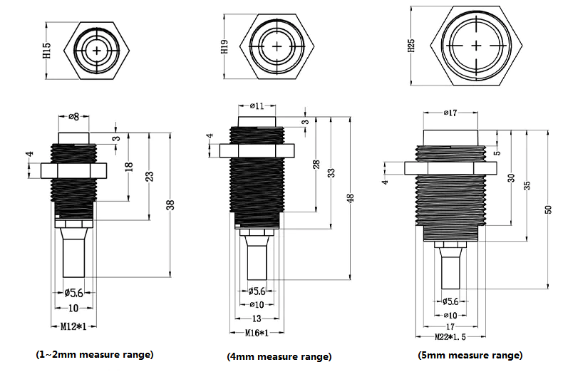
Standard probe installation size:
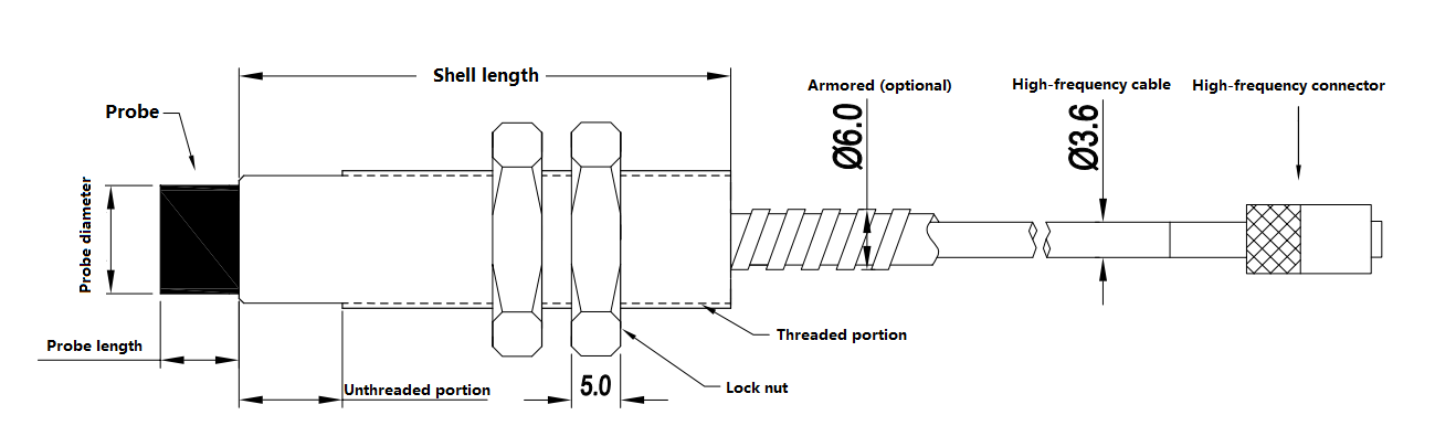
Usually the probe consists of a coil, a head, a shell, a high-frequency cable and a high-frequency connector.
In the production process, the head body of the probe is generally made of high temperature resistant PPS engineering plastics, and the coil is sealed by "secondary injection molding". The probe can work reliably in harsh environment. Because the diameter of the head coil determines the linear range of the sensor system, we usually use the external diameter of the head body to classify and characterize each type of probe. In general, the linear range of the sensor system is roughly 1/2 ~ 1/4 times of the diameter of the probe head. The sensor probe of ML33 series is shown in the figure (standard type) :
Measuring range | Probe diameter | Probe length | Shell length | Installation type | Thread specification |
1mm | Φ6mm | 5mm | 30mm | Standard | M8X1.0 |
2mm | Φ8mm | 7mm | 30mm | Standard | M9X1.0 |
4mm | Φ11mm | 8mm | 50mm | Standard | M14X1.5 |
5mm | Φ17mm | 11mm | 50mm | Standard | M18X1.0 |
12.5mm | Φ30mm | 26mm | 40mm | Reverse setting | M14X1.5 |
20mm | Φ40mm | 33mm | 40mm | Reverse setting | M14X1.5 |
25mm | Φ50mm | 42mm | 50mm | Reverse setting | M18X1.5 |
50mm | Φ60mm | 47mm | 50mm | Reverse setting | M18X1.5 |
The probe housing is used to connect and secure the probe head and is used as a clamping structure for the probe installation. The shell is usually made of brass nickel-plated process, engraved with standard threads and equipped with lock nuts. In order to adapt to different applications and installation occasions, the probe housing has different forms and different threads and dimensions.
Mounting size of countersunk probe:
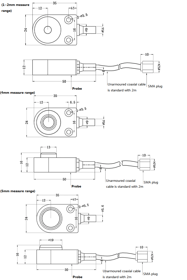
Installation size of square probe:
Round probe mounting size: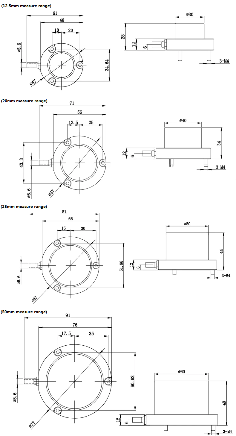
Eddy current sensor preprocessor
The preprocessor is the signal processing center of the whole sensor system. On the one hand, the preprocessor provides high frequency AC excitation current to the probe coil to make the probe work; On the other hand, the preprocessor induces the gap change between the probe head body and the metal conductor in front of the head body through a special circuit. After processing by the preprocessor, the voltage or current output signal changes with the linear change of the gap.
Outline size of ML33 series preprocessor:

Product naming rules
1、Probe
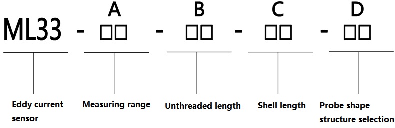
● A □□:Probe range code selection
▼ Probe code classification
Code | 01 | 02 | 04 | 05 | 12 | 20 | 25 | 50 |
Measuring range | 1mm | 2mm | 4mm | 5mm | 12.5mm | 20mm | 25mm | 50mm |
● B□□ :No thread length option
he threaded part of the probe is to facilitate installation, reduce invalid thread length, and make screwing bolts faster
▼Metric threaded probe
Minimum unthreaded length 0mm | 0 | 0 |
Maximum unthreaded length 250 mm | 2 | 5 |
Increase by 10 mm | 0 | 1 |
● C □□ Shell length selection
The length of the probe shell depends on the use of the site, in order to ensure the measurement accuracy, avoid the vibration of the probe rod to bring measurement interference, it is recommended not to use more than 300mm long shell length; When necessary, a mounting attachment for strengthening the probe rod should be attached.
▼Metric shell length
Minimum shell length 20mm | 0 | 2 |
Maximum shell length 250 mm | 2 | 5 |
Increase by 10 mm | 0 | 1 |
● D □□:Probe shape structure selection
This option does not represent the standard probe structure; C is for countersunk structure. Choose F to represent the square probe structure, choose Y to represent the circular probe structure.
Preprocessor naming rules
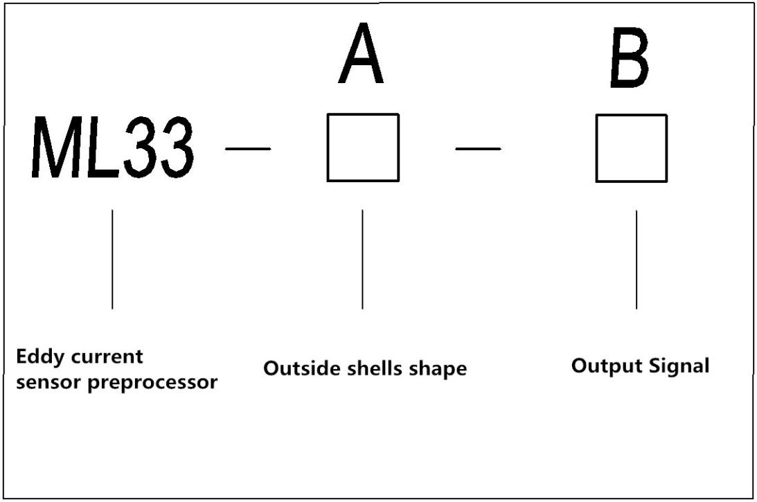
● A □ Preamplifier shell selection
A: Type A shell
B: Type B shell
R: RS485 exclusive use
● B □ Output mode selection
A: Represents the current 4-20ma output +24 V DC power supply
V1-1: Represents a voltage of 0-5v output ±15V DC power supply
V1-2: Represents a voltage of 0-5v output +12V DC
V1-3: Represents a voltage of 0-5v output +24V DC power supply
V2-1: Represents a voltage of 0-10v output ±15V DC power supply
V2-2: Represents a voltage of 0-10v output + 12V DC power supply
V2-3: Represents a voltage of 0-10v output + 24V DC power supply
R: Represents RS485 output +12V DC power supply
Installation of probe
When installation the probe, you should pay attention to the following issues:
口The distance between the probe 口Distance between probe and mounting surface
口Mounting bracket selection 口Probe mounting clearance
口Installation of cable with probe 口Sealing and insulation of cable adapters
口Corrosion resistance of the probe 口High pressure environment of probe
●The distance between the probes
When the probe head coil through the current, there will be alternating magnetic field around the head, so pay attention to the installation of the two probes can not be too close, otherwise the two probes will interfere with each other through the magnetic field (as shown in the following figure between the probe distance), the output signal superimposed on the two probes of the difference frequency signal, resulting in distortion of the measurement results, This is called adjacent interference. Factors related to the exclusion of adjacent interference: the shape of the measured body, the diameter of the probe head and the installation mode. The minimum distance between probes in general is shown in the table below.
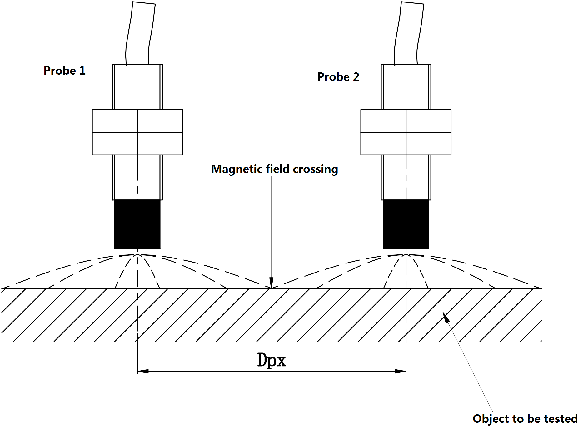
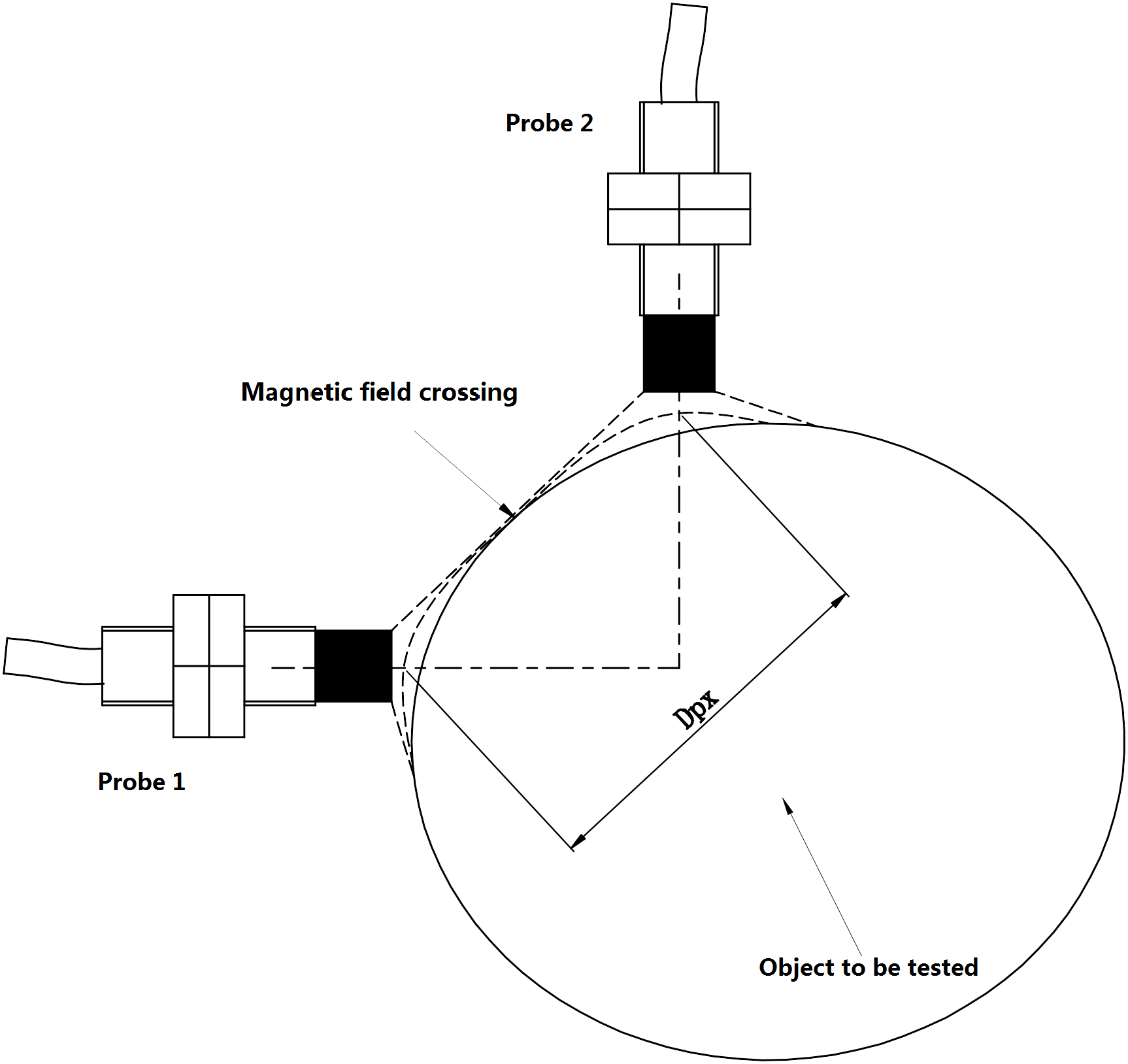
Probe diameter (mm) | Two probes are mounted in parallel Dpx(mm) | Two probes are mounted vertically(The object under is circular) DCv(mm) | Two probes are mounted(The object under is square) DCF(mm) |
Φ6mm | 40.6 | 35.6 | 22.9 |
Φ8mm | 40.6 | 35.6 | 22.9 |
Φ11mm | 80 | 70 | 40 |
Φ17mm | 100 | 80 | 50 |
Φ30mm | 160 | 130 | 90 |
Φ40mm | 180 | 160 | 100 |
Φ50mm | 200 | 180 | 150 |
Φ60mm | 300 | 200 | 180 |
●Distance between probe head and mounting surface
The alternating magnetic field emitted by the head of the probe has a certain radial and transverse diffusion. Therefore, during installation, it is necessary to consider the influence of metal conductor materials on the installation surface, and ensure that the head of the probe is not less than a certain distance from the installation surface. The engineering plastic head body should be completely exposed to the installation surface, otherwise the installation surface should be processed into a flat bottom hole or chamfer, as shown in the following figure.
1. Select the sensor according to the range of the measuring position, the environment and size of the installation space, and the characteristics of the measured body material, and check whether the appearance of each part of the sensor is intact and whether each part is supporting (such as whether the diameter of the probe is consistent with the diameter of the supporting probe stipulated in the preprocessor type number, whether the cable length of the probe is in line with the requirements of the cable length of the preprocessor, etc.). Sensors ordered in complete sets are usually provided with a data verification sheet when leaving the factory, which indicates the model and number of each part of the sensor for matching calibration, so that users can check with the marks on the product according to it. Then, specific marks are made on the probe and preprocessor of the sensor respectively.
2. The probe cable connector is connected with the internal circuit, and does not have the sealing property. In order to avoid contact between the joint and the casing and to strengthen the tightness, the joint should be heated and shrink-wrapped with a heat shrink sleeve. This can also play a role in preventing the joint from loosening. Do not use sticky electrical tape to insulate the joint, as oil mist can dissolve the adhesive on the tape and contaminate the joint.
3. Once the length of the probe cable is selected, it can not be shortened or lengthened at will when in use. Too long cable can not be cut at will, otherwise it may cause the sensor to be seriously out of tolerance or not work normally. The probe cable length shall be the same as the cable length required by the preprocessor. Except for special specifications.
4, connect all parts of the sensor, power check the sensor, if out of tolerance, it needs to be recalibrated. During inspection, special attention should be paid to whether the material of the test piece is consistent with the material of the measured body or has similar composition.
5. If the supporting installation bracket has not been ordered, the appropriate installation bracket should be processed by itself. The external installation of the probe bracket is more complex, generally should be ordered.
6, in the frame processing support installation bracket of the screw hole, the internal installation of the probe bracket generally need two screw holes for fastening, the external installation of the probe is generally in the shell processing with threaded through holes.
7. Tighten and install the probe bracket. If the probe is installed externally, the probe should be first secured to the bracket, and then the bracket is screwed into the mounting hole.
8, adjust the probe installation clearance. The initial installation clearance of the probe has different requirements for different purposes.
9. Tighten and install the probe. For the internal installation of the probe, if the Angle bracket is used, the back is tightened with two nuts, and the clamping block is locked with fastening screws; For external mounting probes, tighten external mounting brackets. Fastening screws and nuts should be equipped with spring washers to prevent loosening.
Probe installation
The requirements of the working environment of the transmitter is much stricter than that of the probe, and it is usually installed away from the danger zone. The surrounding environment should be free of corrosive gases, dry, small vibration, and the ambient temperature is not much different from room temperature. Installation beside the machine, in order to ensure the transmitter safe and reliable work, it is necessary to use a special installation box. In order to prevent the interference caused by different ground potentials, it is necessary to use single point grounding.
Matters need attention
1.Requirements for probe mounting clearance
When installing the probe, the linear measurement range of the sensor and the change of the measured gap should be considered. When the total change of the measured gap is close to the linear working range of the sensor, it is especially important to pay attention to (the linear range of the selected sensor should be greater than 15% of the measured gap when ordering the selection). Generally, when vibration is measured, the installation gap of the probe is located at the linear midpoint of the sensor; When measuring displacement, it is necessary to determine the setting of the installation clearance according to the change in which direction or the change in which direction is larger. When the displacement changes away from the probe end, the installation clearance should be set at the linear near end; Otherwise, it should be located at the far end of the linear.
The following methods can be used to adjust the probe installation clearance
Connect the probe, extension cable and preprocessor, connect the sensor system power supply, monitor the output of the preprocessor with a multimeter voltage file, and adjust the gap between the probe and the measured surface. When the output of the preprocessor is equal to the voltage or current corresponding to the installation gap (the value can be obtained from the sensor calibration data sheet), tighten the two fastening nuts of the probe.
Measuring the output voltage of the preprocessor to determine the mounting gap may give the illusion that the output of the preprocessor is equal to the voltage or current output value corresponding to the mounting gap because of the metal surrounding the mounting hole when the probe head is not exposed. With the probe adjusted to the correct mounting position, the output of the preprocessor should be: First, the larger saturation output (the probe is not yet put into the mounting hole), then the smaller output (the probe is put into the mounting hole), continue to plug the probe into the mounting hole, the output of the preprocessor will change to the maximum output (the probe head is exposed to the mounting hole, but the gap between the probe and the measured surface is larger), and then continue to plug the probe. The output of the preprocessor is equal to the value corresponding to the installation gap, and the probe is the correct installation Gap.
2.Requirements for initial clearance
Various models of eddy current sensors, are in a certain gap voltage value of its reading has a good linearity, so in the installation of sensors must adjust the appropriate initial gap, characteristics of each set of products will be tested, draw the corresponding characteristic curve, engineering and technical personnel in the use of sensors must carefully study the matching verification certificate, Carefully analyze the characteristic curve to determine whether the sensor meets the gap to be measured. Generally, the larger the diameter of the sensor, the larger the gap to be measured.
3.Requirements for probe bracket
The eddy current sensor is installed on the fixed support, so the quality of the support directly determines the measurement effect, which requires that the support should have enough stiffness to improve the natural vibration frequency, avoid or reduce the vibration of the support when the measured body vibrates. The natural vibration frequency of the support should be at least 10 times of the mechanical rotation speed, and the support should be parallel to the tangent direction of the measured surface. The sensor is mounted vertically on the bracket. Although the center line of the probe has no effect on the system characteristics when it is tilted 15° in the vertical direction, it is best to ensure that the sensor is perpendicular to the surface being measured.
4.The influence of the measured material on the measurement results of the sensor
The characteristics of the sensor are related to the conductivity and permeability of the measured body. When the measured body is a magnetic material (such as ordinary steel, structural steel, etc.), eddy current effect and magnetic effect exist at the same time, and the magnetic effect reacts on the eddy current effect, so the eddy current effect is weakened, that is, the sensitivity of the sensor is reduced. However, when the measured body is a weak magnetic conductive material (such as copper, aluminum, alloy steel, etc.), due to the weak magnetic effect, the eddy current effect is stronger, so the sensor sensitivity is higher.
Copper: 14.9V/mm
Aluminum: 14.0V/mm
Stainless steel(1Cr18Ni9Ti): 10.4V/mm
45# steel: 8.2V/mm
40CrMo steel: 8.0V/mm
5.The influence of surface machining status of the measured body on the measurement results of the sensor
The surface finish of the measured body facing the probe will also affect the measurement results! Non-smooth surface of the measured body will bring large additional errors in practical measurement applications. Especially for vibration measurement, error signals are superimposed with actual vibration signals, and it is difficult to separate them electrically. Therefore, the measured surface should be smooth and clean. There should be no nicks, holes, boss, groove and other defects (except boss or groove specially set for key phase, speed measurement). Generally, the roughness of the surface measured for vibration measurement is between 0.4um and 0.8um; For displacement measurement, the measured surface roughness is required to be between 0.4um and 1.6um. If not, the surface to be measured needs to be refined or polished.
6.The influence of residual magnetic effect on the sensor
The eddy current effect is mainly concentrated on the surface of the measured body. If the residual magnetic effect is formed in the processing process, the characteristics of the sensor will be affected by uneven quenching, uneven hardness, uneven microstructure and uneven crystal structure. During vibration measurement, if the residual magnetic effect on the surface of the measured body is too large, the measurement waveform will be distorted.
7.The influence of the surface coating on the sensor
The influence of the coating on the surface of the measured body on the sensor is equivalent to changing the material of the measured body. Depending on the material and thickness of the coating, the sensitivity of the sensor will change slightly.
8.The influence of the surface size of the measured body on the sensor
The range of magnetic field generated by the probe coil is certain, and the eddy current field formed on the surface of the measured body is also certain. In this way, there are certain requirements on the surface size of the measured body. In order to prevent the magnetic field generated by the eddy current from affecting the normal output of the instrument, a certain range of non-conductive media space must be left around the sensor head during installation. If more than two sensors are installed in a certain part at the same time, it is necessary to consider whether there will be cross interference, and the specified distance between the two probes must be maintained.
Generally, when the surface of the measured body is plane, the point directly opposite the center line of the probe is the center, the diameter of the measured surface should be greater than 1.5 times of the diameter of the probe head; When the measured body is a circular axis and the center line of the probe is orthogonal to the axis line, the diameter of the measured shaft is generally required to be more than 3 times the diameter of the probe head, otherwise the sensitivity of the sensor will decline, the smaller the surface of the measured body, the more the sensitivity will decline. When the surface size of the measured body is the same as the diameter of the probe head, the sensitivity drops to about 72%. The thickness of the measured body will also affect the measurement results. The depth of eddy current field in the measured body is determined by frequency, material conductivity and magnetic permeability. Therefore, if the measured body is too thin, it will cause insufficient eddy current effect, so that the sensitivity of the sensor decreases. Generally, the thickness of steel and other magnetic materials with a thickness greater than 0.1mm and the thickness of copper and aluminum and other weak magnetic materials with a thickness greater than 0.05mm will not be affected by the sensitivity of the thickness.
9.Influence of high frequency coaxial cable on sensor
High frequency coaxial cable is also one of the main factors affecting the electrical performance of eddy current sensors. Since the sensor works at high frequency (oscillation frequency is about 1MHZ), the frequency attenuation, temperature characteristics, impedance and length of the high frequency coaxial cable all become factors that affect the performance of the sensor!
10.Influence of external magnetic field on sensor
Eddy current sensor belongs to inductance sensor, because its main principle is eddy current effect, so, the influence of external magnetic field should be fully considered in engineering application! Strong external magnetic field will definitely affect the performance of the sensor.
l to outside the static magnetic field, as a result of static magnetic field is a certain direction and eddy current magnetic field may present a variety of conditions, and determine when external magnetic field direction, the eddy current magnetic field interference is certain. Therefore, in practical engineering applications, the influence of static magnetic field can be measured through field tests to detect changes in sensor sensitivity, and eliminated through subsequent circuits or software algorithms.
l alternating magnetic field of the external world, such as large exciter, frequent startup of large motor, starter, etc., the direction and the intensity of magnetic field may not be a certain value, thus produced by the alternating magnetic field on the influence of the eddy current magnetic field and alternating. Therefore, in engineering applications, eddy current sensors should be kept away from the action range of alternating magnetic field as far as possible, or magnetic field shielding measures should be adopted to minimize the impact.