


Product Summary:
The principle of eddy current displacement sensor system is eddy current effect, which is a kind of inductive measurement principle. The eddy current effect results from the energy of the oscillating circuit. Eddy currents need to be in conductive materials to form. An alternating current is introduced into the coil inside the sensor probe to form a magnetic field around the coil. If a conductor is placed in this magnetic field, an eddy current will be excited in the conductor according to Faraday's law of electromagnetic induction. According to Lenz's law, the magnetic field direction of the eddy current is opposite to the magnetic field of the coil, which will change the impedance value of the coil in the probe. The change of this impedance value is directly related to the distance between the coil and the object being measured. After the sensor probe is connected to the controller, the controller can obtain the change of voltage value from the sensor probe, and calculate the corresponding distance value based on this, and the eddy current measurement principle can measure all conductive materials.
- Product Overview
- Technical Parameters
- Size selection
I. Working principle of eddy current displacement sensor:
The principle of eddy current sensor system is eddy current effect, which is a kind of inductive measurement principle. The eddy current effect results from the energy of the oscillating circuit. Eddy currents need to be in conductive materials to form. An alternating current is introduced into the coil inside the sensor probe to form a magnetic field around the coil. If a conductor is placed in this magnetic field, according to Faraday's law of electromagnetic induction, eddy currents will be excited in the conductor. According to Lenz's law, the magnetic field direction of the eddy current is opposite to the magnetic field of the coil, which will change the impedance value of the coil in the probe. The change of this impedance value is directly related to the distance between the coil and the object being measured. After the sensor probe is connected to the controller, the controller can obtain the change of voltage value from the sensor probe, and calculate the corresponding distance value based on this, and the eddy current measurement principle can measure all conductive materials. Because the eddy current can penetrate the insulator, even the metal material whose surface is covered with the insulator can also be used as the measured object of the eddy current sensor. The unique coil winding design can not only achieve the compact shape of the sensor, but also meet the requirements of its operation in high temperature measurement environment.
II. the scope of application:
By measuring the relative position of the metal body and the probe end, the eddy current displacement sensor is induced and processed into the corresponding electrical signal output. Sensor can work reliably for a long time, high sensitivity, strong anti-interference ability, non-contact measurement, fast response speed is not affected by oil and water and other media, in large rotating machinery shaft displacement, shaft vibration, shaft speed and other parameters for long-term real-time monitoring is widely used. And it has been extended to satellite launch, material identification, weighing measurement, metal plate thickness measurement, material shape variables and other application fields.
Performance parameter
Measure range | 1mm | 2mm | 4mm | 5mm | 12.5mm | 20mm | 25mm | 50mm |
Probe Diameter | Φ6mm | Φ8mm | Φ11mm | Φ17mm | Φ30mm | Φ40mm | Φ50mm | Φ60mm |
Linearity (%FS) | ≤±0.25 | ≤±0.25 | ≤±0.5 | ≤±0.5 | ≤±1 | ≤±1 | ≤±1 | ≤±2 |
Resolution | 0.05um | 0.1um | 0.2um | 0.25um | 0.625um | 1.25um | 1.25um | 2.5um |
Repeatability | 0.1um | 0.2um | 0.4um | 0.5um | 1.25um | 2.5um | 2.5um | 5um |
Frequency Response (-3dB) | 0~10KHz | 0~8KHz | 0~2KHz | 0~1KHz | ||||
Output Signal | 0~5V,0~10V,4~20mA,RS485 | |||||||
Power Supply | Voltage Type:+9~18VDC,+18~36VDC or ±15V~±18VDC | |||||||
Current Type:+22~30VDC,RS485+12VDC | ||||||||
Working Current | Voltage Type:<45mA | |||||||
Current Type:<25mA | ||||||||
RS485<40mA | ||||||||
Ripple Wave | ≤20mV | |||||||
Temperature Drift | According to the output signal and the corresponding range and other factors | |||||||
Static Sensitivity | According to the output signal and the corresponding range | |||||||
Output Load | Voltage Output:Load capacity<10KΩ | |||||||
Current Output:Load capacity<500Ω | ||||||||
Calibration Temperature | (20±5)℃ | |||||||
Working Temperature | Probe:-30℃~+150℃ | |||||||
Converter:-30℃~+85℃ | ||||||||
Protection | Probe: IP67 | |||||||
Converter: IP65 | ||||||||
Probe Cable Length | Standard 2m,(customized) | |||||||
Power Cable Length | Standard 2m,(customized) | |||||||
★System Operating Principle
The principle of sensor system is eddy current effect.When the power supply of the sensor system is connected, a high-frequency current signal will be generated in the preprocessor. This signal will be sent to the head of the probe through the cable. An alternating magnetic field H1 will be generated around the head. Conversely, If a metal conductor material is close to the head of the probe, the alternating magnetic field H 1 will generate an eddy current field on the surface of the conductor, which will also generate an alternating magnetic field H 2 in the opposite direction to H 1.As a result of the reaction of H 2, the amplitude and phase of the high-frequency current in the coil of the probe head will be changed, that is, the effective impedance of the coil will be changed.This change is related not only to the eddy current effect, but also to the magnetostatic effect, that is, to the conductivity of the metal conductor, the permeability, the geometric shape, the geometric parameters of the coil, the excitation current frequency and the distance between the coil and the metal conductor.The coil is assumed to be homogeneous and its properties are linear and isotropicThe physical properties of a metal conductor system are usually determined by the permeability of the metal conductor, the conductivity, the size factor r, the coil and theMetal conductor distance, coil excitation current intensity I and frequency and other parameters to describe. Therefore, the impedance of the coil can be expressed by the function Z=F(clock,,r,I,).If the control constant,, r,, I,, then impedance Z becomes the distance delta of the single-valued function, by maxwell's formula, this function can be obtained as a nonlinear function, its curve is the "S" curve, in a certain range can be approximated as a linear function.


★Application range of eddy current displacement sensor
By measuring the position of the metal body relative to the probe, the eddy current displacement sensor is induced and processed into the corresponding electrical signal output. Sensors can be long-term and reliable work, high sensitivity, strong anti-jamming capability, non-contact measurement, fast response speed degree, is not affected by water medium, in large rotating machinery shaft displacement, shaft vibration, parameters such as spindle speed is widely used for long-term real-time monitoring, and is extended when satellite launch, material identification, weighing, metal thickness measurement, application fields such as material shape variables.
★Complete sensor system composition
A complete sensor system mainly consists of probe, preprocessor and accessories. The system composition is shown in the following figure:


Typical structure of probe
In the process of production, the probe head body is usually made of high temperature resistant PPS engineering plastic or high temperature resistant ptfe, and the coil is sealed by "secondary injection". Make the probe work reliably in harsh environment. Since the coil diameter of the head body determines the linear range of the sensor system, we usually use the external diameter of the head body to classify and characterize various types of probes. Generally, the linear range of the sensor system is roughly 1/2 ~ 1/4 of the diameter of the probe head. ML33 sensor series, a total of Φ6,Φ8,Φ11,Φ17,Φ30,Φ40,Φ50,Φ60 a total of 8kinds of the diameter of the head as shown in figure shown below:
Name | Code Number | Measuring range | Installation type | thread specification |
∮6mm Probe | 01 | 1mm | Standard | M8X1 |
∮8mm Probe | 02 | 2mm | Standard | M9X1 |
∮11mm Probe | 04 | 4mm | Standard | M14X1.5 |
∮17mm Probe | 05 | 5mm | Standard | M18X1 |
∮30mm Probe | 12 | 12.5mm | Standard | M14X1.5 |
∮40mm Probe | 20 | 20mm | M14X1.5 | |
∮50mm Probe | 25 | 25mm | M18X1.5 | |
∮60mm Probe | 50 | 50mm | M18X1.5 |
Installation Dimension

Type A shell

Type B shell

Model naming specification
●ML33 The sensor system consists of a probe, a front-end, an extension cable (optional) and accessories.

A:Probe range code selection
▼ Probe code classification

● B No thread length option
The non-threaded part of the probe is to facilitate installation, reduce the invalid thread length, and make the screw fastening faster
▼Metric thread probe

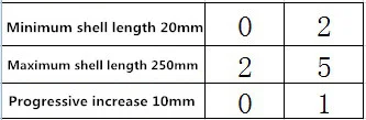
● C Shell length selection
The length of the probe shell is determined according to the field usage. In order to ensure the measurement accuracy and avoid measurement interference caused by the probe rod's own vibration, it is recommended not to use a shell length of more than 300 mm. When it is necessary to use, a mounting attachment to enhance the probe rod strength should be attached.
▼Metric shell length
Front-end naming conventions
●Preposition Model,Specification

●A Preprocessor shell selection
A: Type A shell
B: Type Bshell
● B Output mode selection
A: Represents the current 4-20m output 22-30 VDC power supply
V1-1: Represents a voltage of 0-5v output ±15V DC--±18V DC power supply
V1-2: Represents a voltage of 0-5v output +12V DC power supply
V1-3: Represents a voltage of 0-5v output +24V DC power supply
V2-1: Represents a voltage of 0-10v output ±15V DC--±18V DC power supply
V2-2: Represents a voltage of 0-10v output +12V DC power supply
V2-3: Represents a voltage of 0-10v output +24V DC power supply